Product

Product

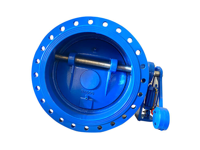
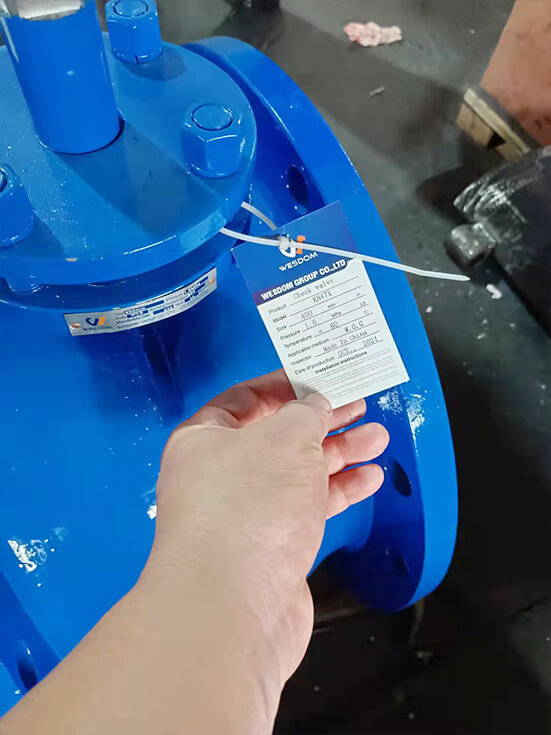
Butterfly buffer check valve
Nominal pass through: 40~1400mm
Nominal pressure: 1.0~2.5MPa
Applicable medium: water, oil, sewage, seawater
Applicable temperature: 0~80℃ (up to 200℃ if necessary)
Flange standard: GB/T 17241.6 GB/T 9113
Test standard: GB/T 13927 AP1598
Butterfly buffer check valve product overview:
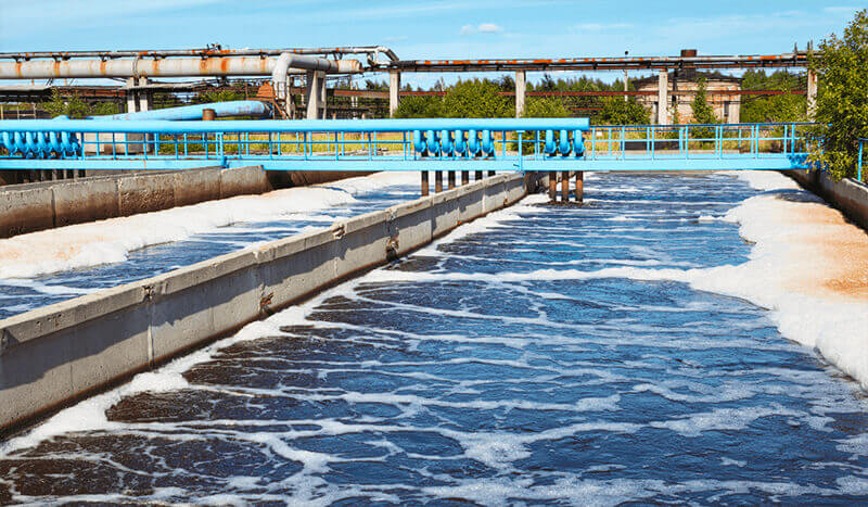
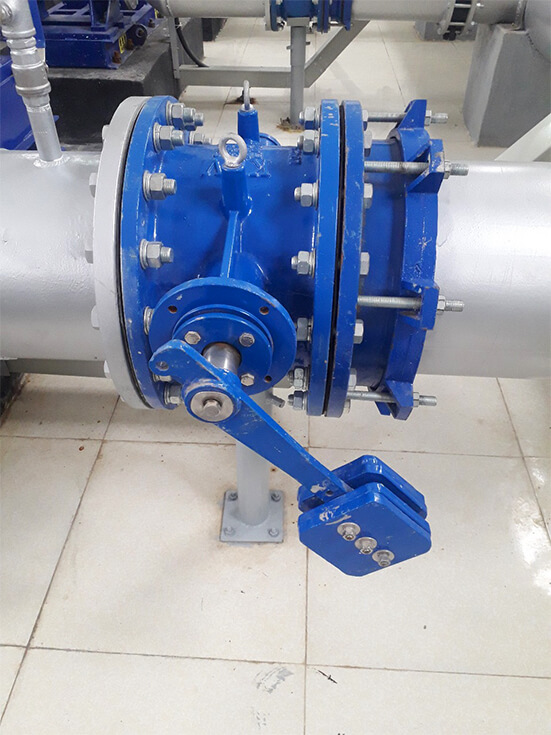
The check valve produced by our factory is mainly used at the pump outlet of industrial water supply and sewage treatment plant to prevent the backflow of the medium in the pipe network. Destructive water hammer is automatically eliminated so that pumps and piping are not damaged. The valve is mainly characterized by valve body, cutting flap and good buffer performance. It is the best product for industrial water and urban sewage.
Butterfly buffer check valves are used on the outlet of the water pump of industrial water supply and sludge treatment plant to prevent the medium inside the pipe network from going back, and remove automatically the destructive water hammer so as to ensure both pump and pipeline not to get damaged. It consists of body, disc, buffer and micro-adjusting valve. And it features by the brand new structure, small volume, small fluid resistance, reliable seal, wearable and good buffering performance. It is really the best product for industrial use of water and city sludge drainage.
Working principle and debugging:
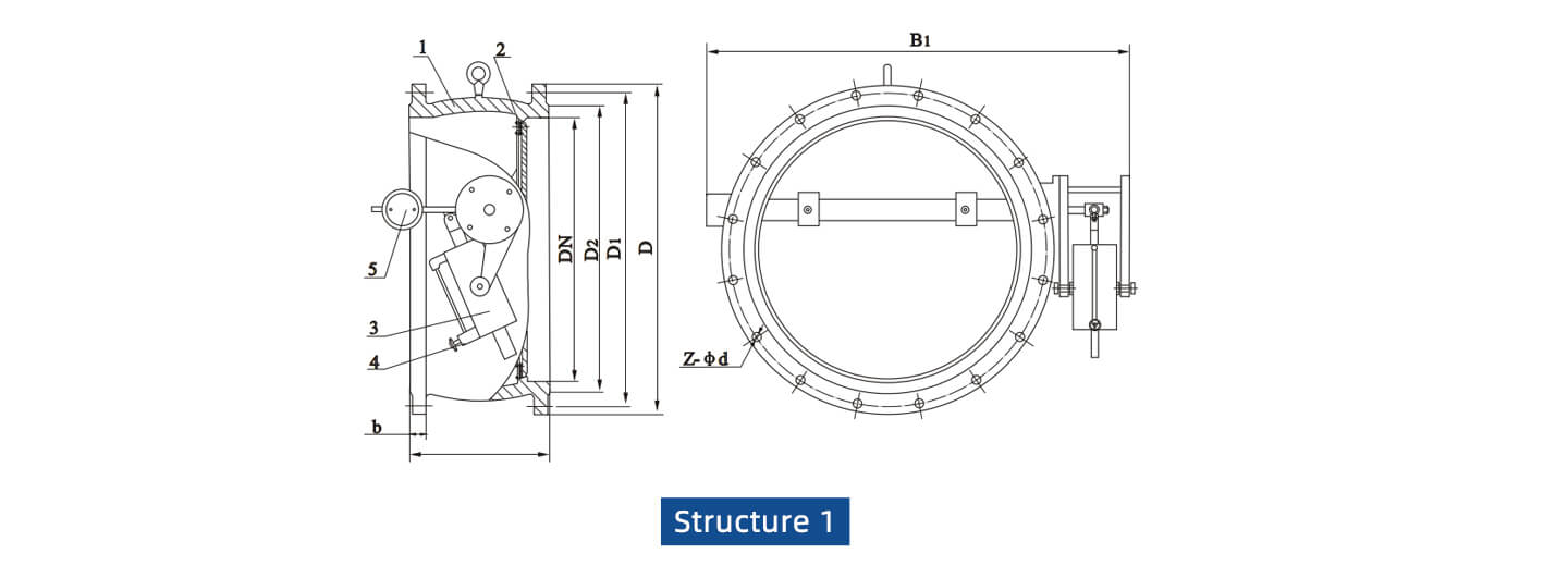
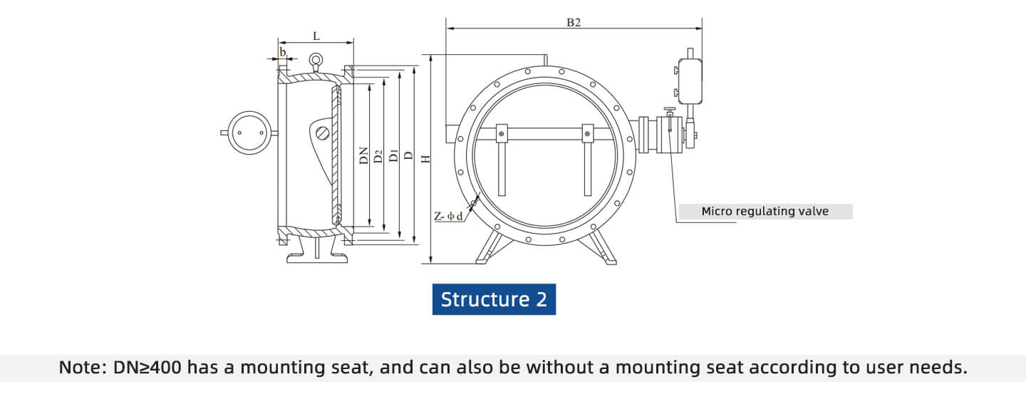
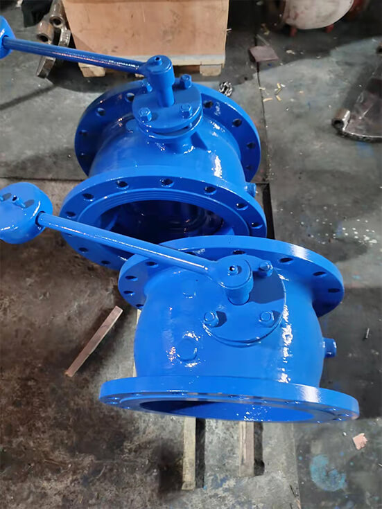
Check valve is mainly composed of valve body, butterfly plate, regulating valve, and buffer cylinder. Buffer cylinder is also composed of two oil chambers, connected internally by a one-way valve, and externally connected by a regulating valve. When the valve is opened, the medium water pushes the butterfly plate.
At this time, the hydraulic oil in the buffer cylinder quickly flows from cavity 1 to cavity 2 through the check valve inside. When the valve is closed, the medium returns to the first cavity.
Due to the large impact force of the counterweight and the high pressure wave, the valve flap is mostly closed, and the oil in the second cavity is compressed at the same time. Normal opening of the regulating valve is only 1/3. The high pressure oil compressed in the 2 cavity can only flow slowly into the 1 cavity through this 1/3 area, so that the valve flap is slowly closed and the pressure of the water hammer peak is weakened. Limits the generation of destructive water hammer.
Due to the function of the above-mentioned regulating valve, the time for the hydraulic oil to flow from cavity 2 back to cavity 1 can be adjusted by adjusting its opening. That is to adjust the closing speed of the valve. Therefore, when the opening degree of the regulating valve is smaller, closing speed of the corresponding valve is slower. Then longer the water discharge, the smaller the water hammer, and vice versa. Users can adjust appropriately according to the needs of the scene.
Material:
| Part Name | Valve body | Valve disc | Valve stem | Filler | Sealing ring |
| Material | Grey cast iron,
Cast steel |
Grey cast iron,
Cast steel, Ductile iron |
Stainless steel | PTFE | Nitrile rubber |
| Pressure
(MPa) |
DN(mm) | L | D | D1 | D2 | b | Z- d | B1 | B2 | H |
|
1.6 |
500 | 350 | 705 | 650 | 608 | 46 | 20-34 | 900 | 1000 | 980 |
| 600 | 390 | 840 | 770 | 718 | 54 | 20-41 | 1090 | 1250 | 1070 | |
| 700 | 430 | 910 | 840 | 788 | 54 | 24-41 | 1200 | 1360 | 1220 | |
| 800 | 470 | 1020 | 950 | 898 | 54 | 24-41 | 1320 | 1480 | 1320 | |
| 900 | 510 | 1120 | 1050 | 998 | 54 | 28-41 | 1420 | 1580 | 1430 | |
| 1000 | 550 | 1255 | 1170 | 1110 | 60 | 28-48 | 1550 | 1700 | 1550 | |
| 1200 | 630 | 1485 | 1390 | 1325 | 66 | 32-54 | 1780 | 1950 | 1800 | |
| 1400 | 710 | 1685 | 1590 | 1525 | 72 | 36-54 | 2000 | 2175 | 1980 | |
| 1600 | 790 | 1930 | 1820 | 1750 | 78 | 40-58 | 2250 | 2470 | 2150 | |
|
2.5 |
100 | 190 | 230 | 190 | 160 | 24 | 8-23 | 280 | 280 | 380 |
| 125 | 200 | 270 | 220 | 188 | 28 | 8-25 | 310 | 310 | 440 | |
| 150 | 210 | 300 | 250 | 218 | 30 | 8-25 | 370 | 370 | 490 | |
| 200 | 230 | 360 | 310 | 278 | 34 | 12-25 | 540 | 600 | 550 | |
| 250 | 250 | 425 | 370 | 332 | 36 | 12-30 | 600 | 700 | 630 | |
| 300 | 270 | 485 | 430 | 390 | 40 | 16-30 | 650 | 740 | 690 | |
| 350 | 290 | 550 | 490 | 448 | 44 | 16-34 | 710 | 800 | 780 | |
| 400 | 310 | 610 | 550 | 505 | 48 | 16-34 | 770 | 870 | 860 | |
| 450 | 330 | 660 | 600 | 555 | 50 | 20-34 | 830 | 920 | 910 | |
| 500 | 350 | 730 | 660 | 610 | 52 | 20-41 | 900 | 1000 | 980 | |
| 600 | 390 | 840 | 770 | 718 | 56 | 20-41 | 1090 | 1250 | 1070 | |
| 700 | 430 | 955 | 875 | 815 | 60 | 24-48 | 1200 | 1360 | 1220 | |
| 800 | 470 | 1070 | 990 | 930 | 64 | 24-48 | 1320 | 1480 | 1320 | |
| 900 | 510 | 1180 | 1090 | 1025 | 66 | 28-54 | 1420 | 1580 | 1430 | |
| 1000 | 550 | 1305 | 1210 | 1140 | 68 | 28-58 | 1550 | 1700 | 1550 | |
| 1200 | 630 | 1525 | 1420 | 1350 | 72 | 32-58 | 1780 | 1950 | 1800 | |
| 1400 | 710 | 1750 | 1640 | 1560 | 78 | 36-65 | 2000 | 2175 | 1980 |

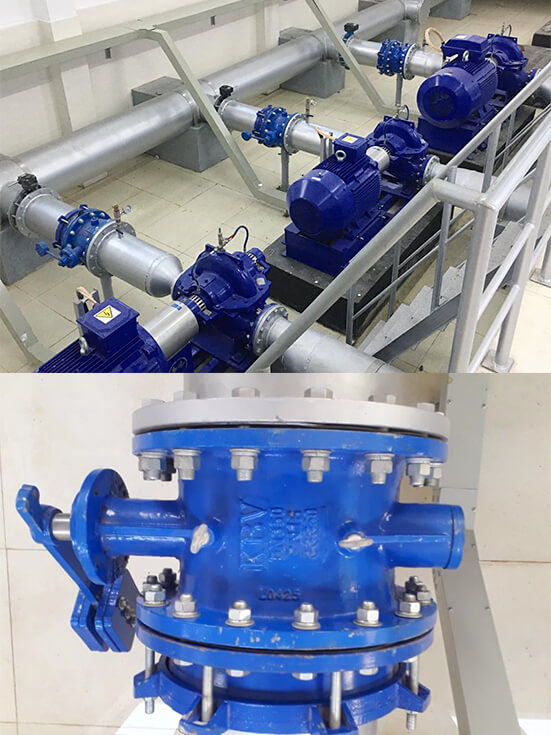
Project description:
WESDOM customizes the most suitable solutions for customers according to the actual needs of customers’ working conditions;
Client feedback:
WESDOM products are of high quality, Now all products have well installed on site.
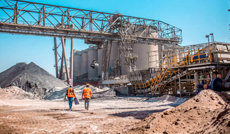
Project pictures:

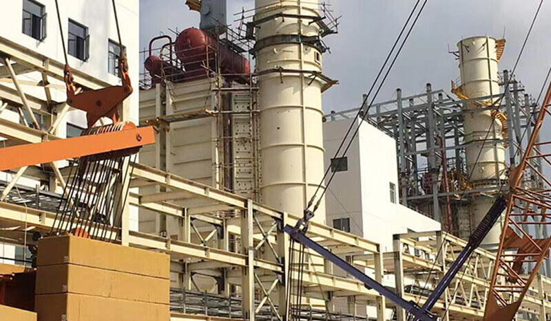
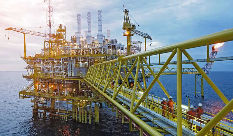
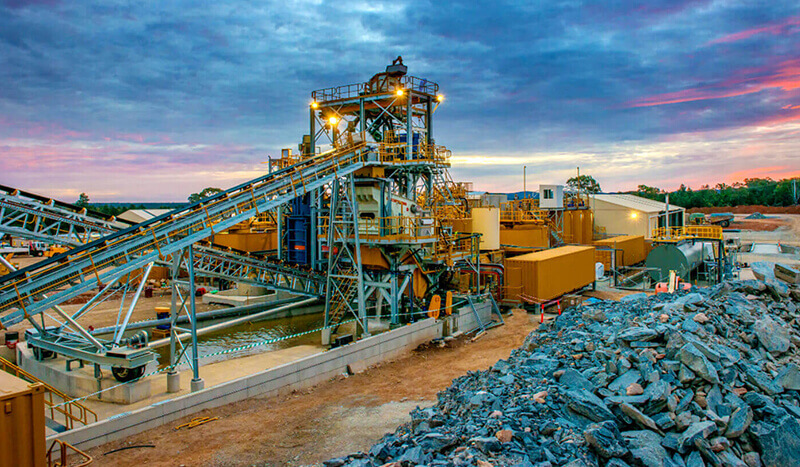
Application