Product

Product

Size: DN50-500
Pressure rating: PN10/PN16
Working temperature: -10~120℃;
Design standard: GB/T 28636-2012, BS7350;
Structural length: GB/T12221 Series 1, EN558-1 Series 1;
Connection flange: GB/T17241.6, ISO7005;
Installation Instructions and Precautions of Static Balancing Valve:
Application:
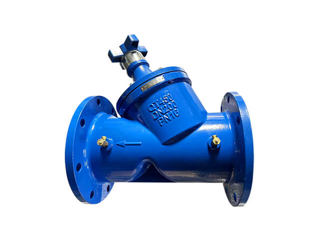
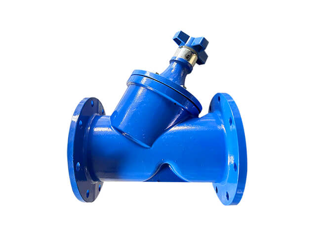
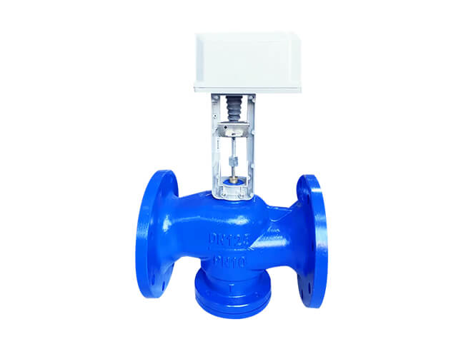
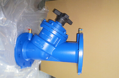
What is Static Balancing Valve?
The static flow balancing valve is designed for achieving hydraulic balance between different loops in a circulation system, allowing for precise flow regulation in each branch or at each terminal.
The CM system balancing valve also functions as an on/off valve and features a reliable opening degree locking memory device. This ensures that after maintenance, the system returns to its original set state, guaranteeing the proper operation of the circulation system according to the initial design conditions. It provides the most reasonable hot and cold values while minimizing energy consumption.
| DN | Inch | L | Kvs | PN16 | ||||||
| φD | φK | nxφd | ||||||||
| DN50 | 2” | 230 | 56 | 165 | 125 | 4-19 | ||||
| DN65 | 21/2″ |
290 |
85 |
185 |
145 |
4-19 |
||||
| DN80 | 3” |
310 |
118 |
200 |
160 | 8-19 | ||||
| DN100 | 4” | 350 | 187 | 220 | 180 | 8-19 | ||||
| DN125 | 5” | 400 | 264 | 250 | 210 | 8-19 | ||||
| DN150 | 6” | 480 | 401 | 285 | 240 | 8-23 | ||||
| DN200 | 8” | 600 | 727 | 340 | 295 | 12-23 | ||||
| DN250 | 10″ | 730 | 1088 | 405 | 355 | 12-28 | ||||
| DN300 | 12″ | 850 | 1276 | 460 | 410 | 12-28 | ||||
| DN350 | 14” | 980 | 2250 | 520 | 470 | 16-28 | ||||
| DN400 | 16” | 1100 | 3050 | 580 | 525 | 16-31 | ||||
| DN450 | 18” | 1200 | 3720 | 640 | 585 | 20-31 | ||||
| DN500 | 20″ | 1250 | 4180 | 715 | 650 | 20-34 | ||||

| NO | Parts Name | Material | ||||
| 1 | BODY | Ductile Iron GGG40 | ||||
| 2 | BONNET | Ductile Iron | ||||
| 3 | SLEEVE | Ductile Iron/SS304 | ||||
| 4 | BOLT | Galvanized Steel | ||||
| 5 | BOLT | Galvanized Steel | ||||
| 6 | WAEHER | Stainless Steel | ||||
| 7 | DISC | Ductile Iron/SS304 | ||||
| 8 | SEALING | EPDM | ||||
| 9 | STEM BARREL | Brass | ||||
| 10 | O RING | EPDM | ||||
| 11 | STEM | Brass/SS304 | ||||
| 12 | BONNET O RING | EPDM | ||||
| 13 | WASHER | Stainless Steel | ||||
| 14 | BOLT | Galvanized Steel | ||||
| 15 | TESTING POINT | Brass | ||||
| 16 | WASHER | Stainless Steel | ||||
| 17 | BOLT | Galvanized Steel | ||||
| 18 | HANDWHEEL | ABS/DI | ||||
| 19 | CIRCLIP | Stainless Steel | ||||
| 20 | O RING | EPDM | ||||
| 21 | O RING | EPDM | ||||
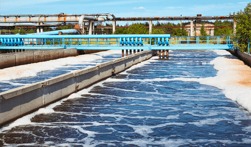
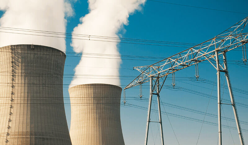
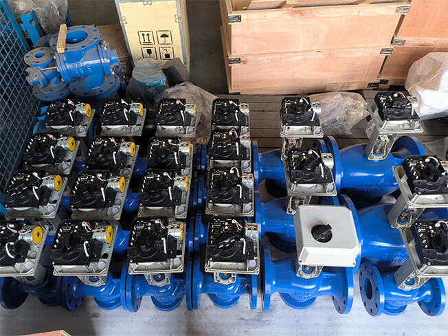
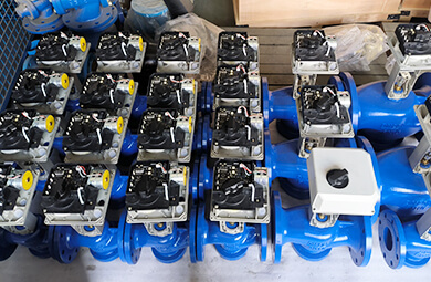
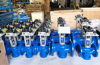
System Application of Static Balancing Valve:
CM series balancing valves can be widely used in heating and cooling systems, domestic water systems, cold tower circulation systems, dehumidification and other hydraulic circulation systems. It calculates the resistance of the primary main pipeline and each graded pipeline, and then uses a differential pressure gauge to measure and adjust the Kvs value to balance the resistance and distribute the flow.
It is used in conjunction with a differential pressure control valve to stabilize the pressure difference between the supply water and the return water, automatically eliminate the interference of system pressure changes, and keep the pressure difference between the static balancing valve and the differential pressure control valve within a stable value. This ensures that the valve downstream of the return water will not produce overflow or water shortage to achieve the best working state.
Installation Instructions and Precautions of Static Balancing Valve:
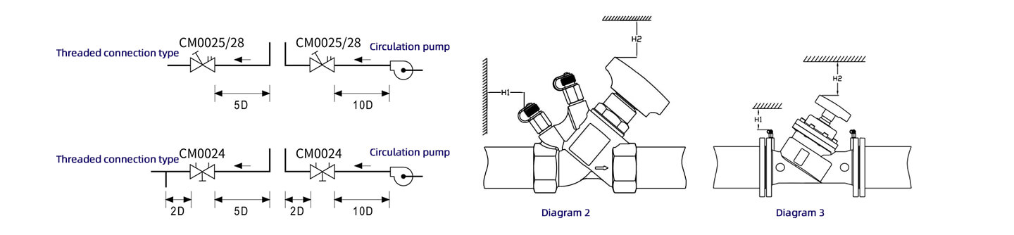
① The balancing valve should be installed in a location where manual adjustment, pressure difference/flow measurement, and draining are convenient. It can be installed either horizontally or vertically. To ensure more accurate balancing flow, a straight pipe section must be installed at both the upstream and downstream ends of the valve. The required length of the straight pipe is shown in the diagram. The valve must be installed following the flow direction indicated by the arrow on the valve body.
② Before installation, remove the flange sealing cover and ensure there are no debris in the system.
③ Ensure that the flow direction of the medium aligns with the direction marked on the valve body.
④ The valve body installation direction is flexible, and the balancing valve can be installed either on the supply or return pipeline. Only one valve needs to be installed per loop. It is recommended to install the balancing valve on the return pipeline with lower water temperature.
⑤ The balancing valve on the main pipeline should be installed in the direction of the pump outlet. The degree indicator on the handle should face the direction visible to the commissioning personnel for easier adjustment. Ensure that no obstacles are in front of the measurement port on the valve body to avoid obstructing the connection of testing instruments during commissioning.
⑥ Ensure sealing between flanges. The measuring port should be installed before the valve is filled with water.
⑦ Once the valve opening degree is set, do not alter it at will. The balancing valve has a shut-off function, eliminating the need for additional shut-off valves.
⑧ To prevent damage to the pressure test port, it should only be installed after the valve is fully mounted. During installation, follow the principle that the red end is for the supply side, and the blue end is for the return side.
⑨ To ensure proper operation, when CM0024/25/28 valves are connected to elbows or pumps, a certain length of straight pipe must be kept. When connected to an elbow, follow the 5D rule before the valve and 2D rule after the valve. When connected to a pump, follow the 10D rule. See Diagram 1.
When installing the valve, leave sufficient space for adjustments as shown in Diagram 2 and Diagram 3:
DN15-DN50: H1 > 200mm, H2 > 170mm
DN50-DN150: H1 > 200mm, H2 > 230mm
DN50-DN150: H1 > 200mm, H2 > 400mm
Application: