Product
Product

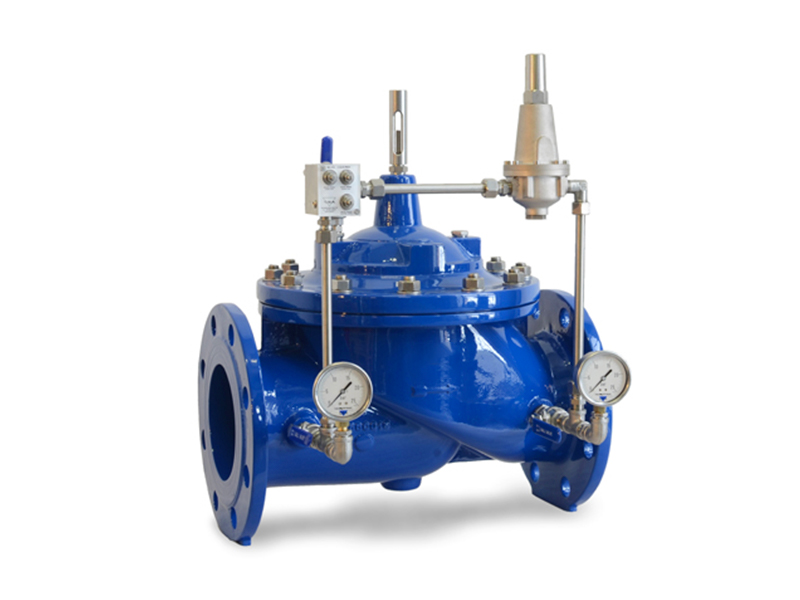
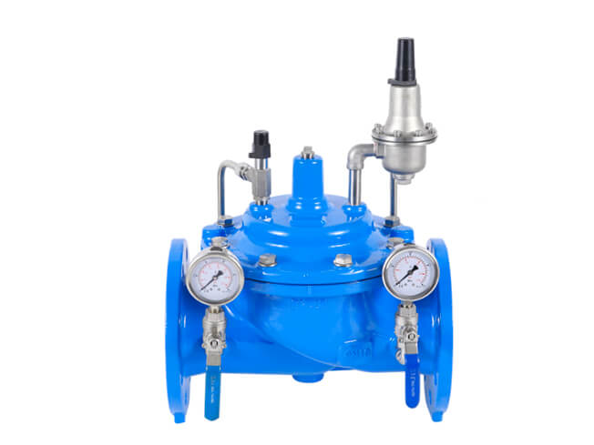
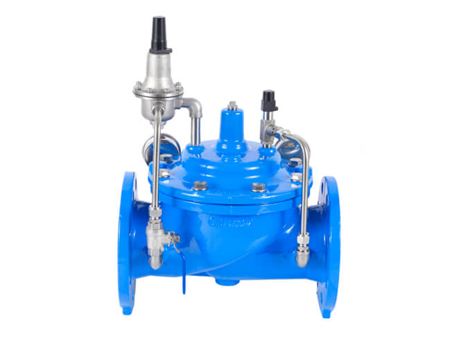
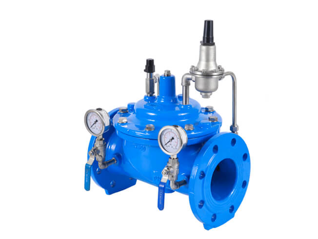
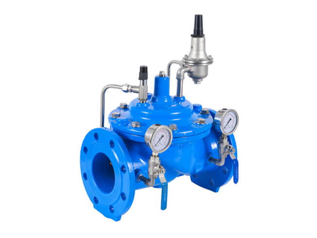
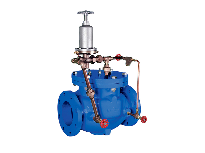
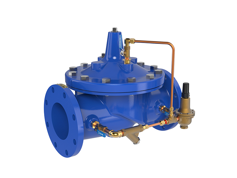
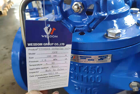
Pressure reducing valve
Flange standard:EN1092-2, BS4504
Valve Test:EN12266
Face to Face Length: BS EN558
Inspection Standard:EN13709-2002
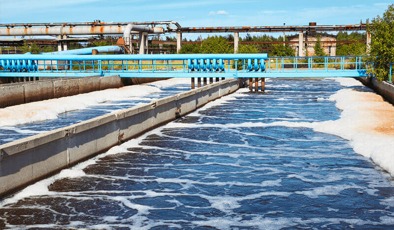
Application medium:Water
Application Temperature:<=80℃
Applied projects:Water conservancy construction
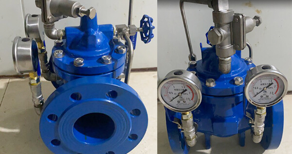
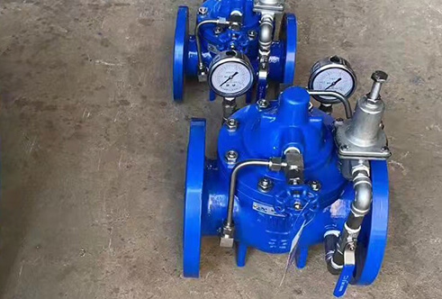
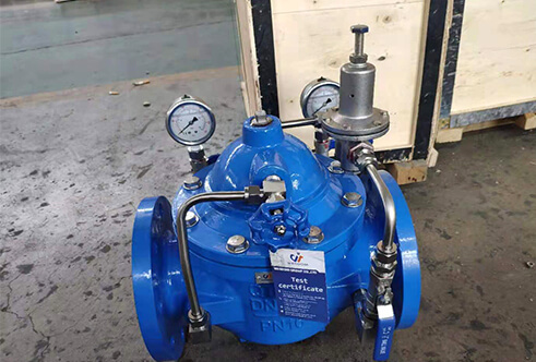
Pressure reducing valve is a globe pattern hydraulically operated automatic control valve that reduces and stabilizes the downstream pressure to a constant value, regardless of variation in demands and upstream pressure conditions.
The piston type multi -function pump control system Is the intellient valve installed In the outlet of the pump outlet of the large- -caliber water supply pipe network, preventing the backflow of the medium, waiter hammer and water hammer, The valve has three functions of electric valve, reverse stop valve and water hammer eliminator,which can effectively improve the safety and ability of water supply system.
Double Chambers and double disc structure can make the valve after the pump stopped quickly closed90% (to prevent the back flow medium pump inversion), and then aiowly Closing the remaining 10% (eliminate destructive water hammer) piston valve ls reliable In performance, high strength, smooth movement, prevent pumping water hammer and 8top the pump water hammer, The valve can automatically realize the opening and closing according to the operating procedures of the pump motor, and the discharge volume and pressure loss are small.
It is not an uncommon practice to use flow restricting valves in an effort to reduce and/or control pressure in even the most sophisticated industrial cleaning machines. Reducing Pressure – Which is it?” the risks of using flow restricting valves to control pressure were discussed in some detail.
Reliable pressure control can only be provided by pressure reducing valves with a feedback mechanism or back pressure controlling valves.
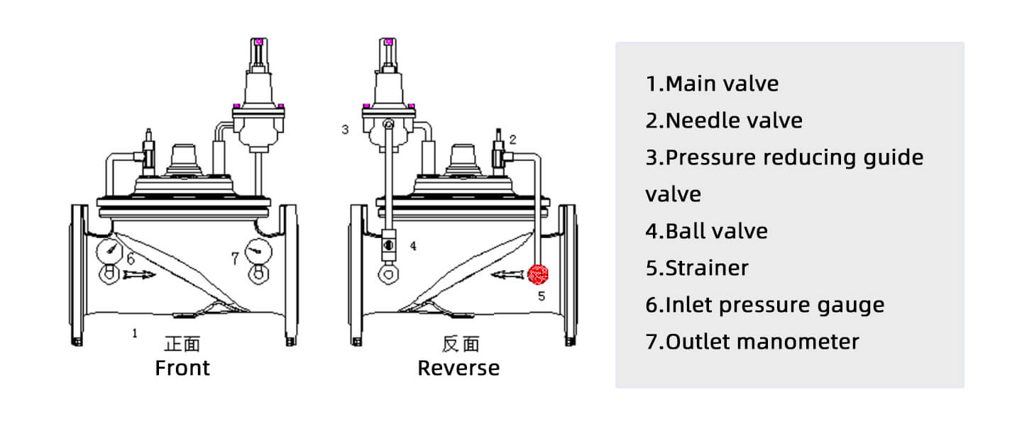
In order for a valve to control pressure, it needs to be able to sense the output pressure and adjust an orifice within the valve to maintain the desired pressure. Although there are hundreds (or maybe thousands) of ways this can be done, the following illustration is representative of most of them.
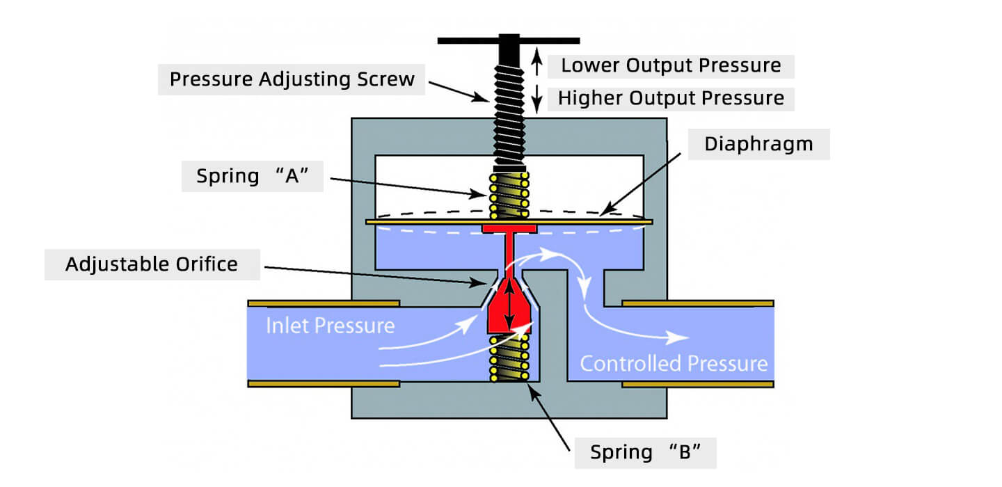
In one type of pressure reducing valve, a diaphragm flexes in response to the pressure on the outlet side of the valve. This diaphragm is attached to the moving part of a variable orifice valve. The movement of the diaphragm is counteracted by two springs and an adjustable screw to adjust the output pressure.
Product features:
①Body and cover in ductile cast iron GJS 450-10.
②Internals in ductile cast iron GJS 450-10 and stainless steel.
③Position indicator in stainless steel.
④Circuitry in stainless steel.
⑤Unit flow regulator device, needle valves and flow stabilizers in stainless steel.
⑥ Seat in stainless steel.
⑦Painting with fluidized bed technology RAL 5005.
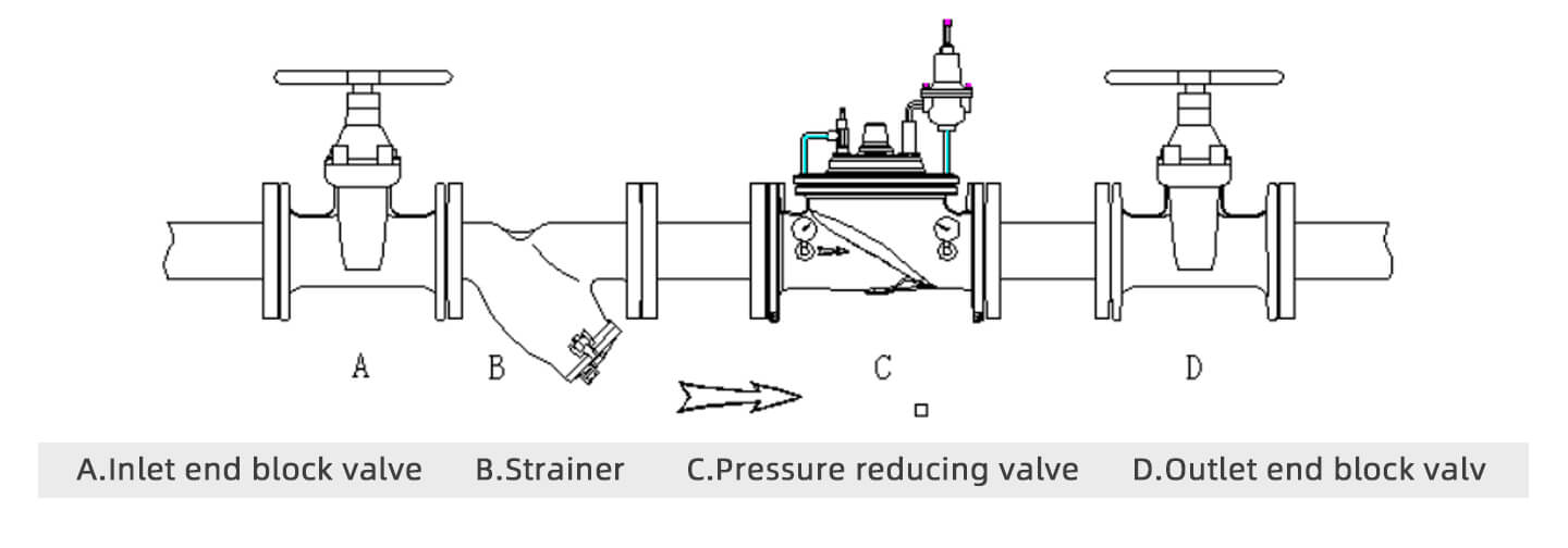
Installation notes:
①Confirm the installation direction of valve
②Install the partition valve before and after the pressure reducing valve
③A filter must be installed in front of the pressure reducing valve
④After the installation of the pressure reducing valve, the pipeline must be cleaned before formal use.
⑤The piping and guide valves of the pressure reducing valve shall not be collided during installation.
Standard and connections:
(1) Design and testing according to EN 1074.
(2)Flanges size from DN 50 to DN 400 mm, higher on request.
(3)Flanges standard EN 1092/2, different on request.
Working conditions:
(1)Pressure range: 10-16-25 bar.
(2)Minimum working pressure: 0.7 bar acting on the pilot.
(3)Treated water maximum 70°C, higher temperature on request.
Operation:
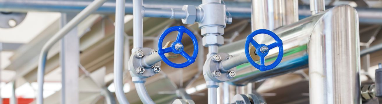
①Open all the ball valves in the pressure reducing valve piping system and open the small blue handwheel on the needle valve.
②Loosen the lock nut on the pilot valve.
③The pressure at the back end of the pressure reducing valve from the factory is 10 bar, compare the actual pressure displayed with the required outlet pressure on site; if the outlet pressure needs to be increased, turn the adjusting screw clockwise; if not, turn the adjusting screw counterclockwise (counterclockwise adjustment requires the water in the pipe to be flowing dynamically, if the water is static, empty the water).
| The pressure increased or decreased with each rotation
of the adjusting screw(bar) |
|
| PN16 | 0.49 |
| PN25 | 1.94 |
Note :That this adjustment of outlet pressure is only for rough adjustment, and the precise adjustment must be made when the pipeline system is carrying through fluid.
①Slowly open the inlet isolation valve to fill the pressure reducing valve with fluid.
②Loosen the plug at the uppermost end of the pressure reducing valve, bleed off the air and screw it back on.
③Gently open the isolating valve at the outlet end to create a small flow in the pipework.
④Slowly adjust (half a turn at a time) the adjusting screw on the guide valve until the desired outlet pressure is reached;
①Open the inlet cut-off valve slowly to fill the pressure reducing valve with fluid;
②Loosen the plug at the top of the pressure reducing valve, drain the air, and then screw it up again;
③Slightly open the outlet end of the partition valve, so that the pipeline system to produce a small flow;
④Slowly adjust the adjusting screw on the guide valve (turn half a turn at a time) until the desired outlet pressure.
Philippines Water Project
Main Products:
200X Pressure reducing valve
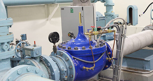
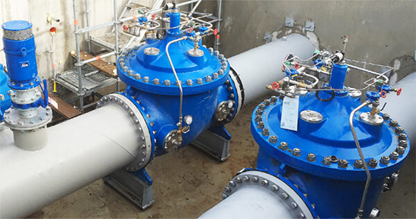
Application
Downstream of pumps to reduce the pressure on the main supply line.
①In derivation from the main line to stabilize the pressure of secondary line and water users.
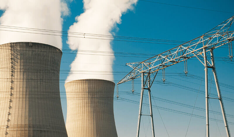
②As a protection against rise in pressure of industrial equipment, plants and civil installations.
③On the inlet supply line of storage tanks to stabilize pressure and flow required for the level control.