Case
Home / Case / Experience / Six common ways to install valves in pipelines
Case
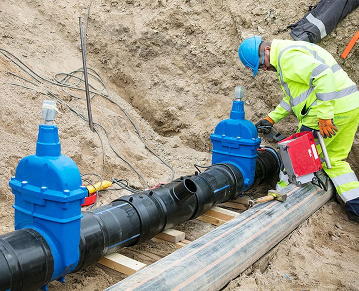
Valves are pipeline accessories used to open and close pipelines, control flow direction, adjust and control the parameters (temperature, pressure and flow) of the conveying medium. It is a control component in the fluid conveying system, with the functions of cut-off, adjustment, flow diversion, reverse flow prevention, pressure stabilization, flow diversion or overflow pressure relief. Valves used in fluid control systems range from the simplest cut-off valves to various valves used in extremely complex automatic control systems, with a wide variety of varieties and specifications. Improper installation and use will directly affect the normal operation in the future, so attention must be paid.
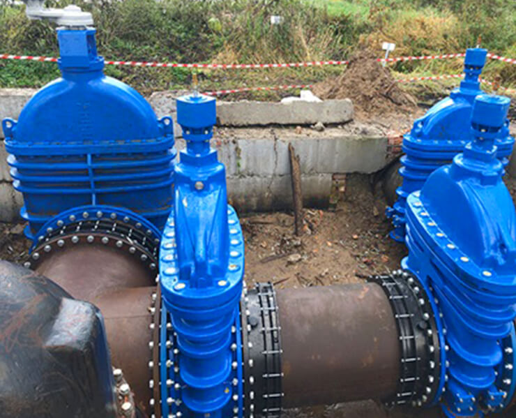
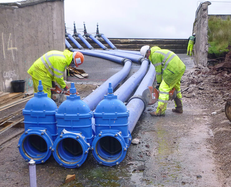
Also known as the gate valve, it is a valve that uses a gate to control the opening and closing, and adjusts the flow of the pipeline and the opening and closing of the pipeline by changing the cross section.
Gate valves are mostly used for pipelines that are fully open or fully closed for fluid media. Gate valve installation generally has no directional requirements, but it cannot be inverted.
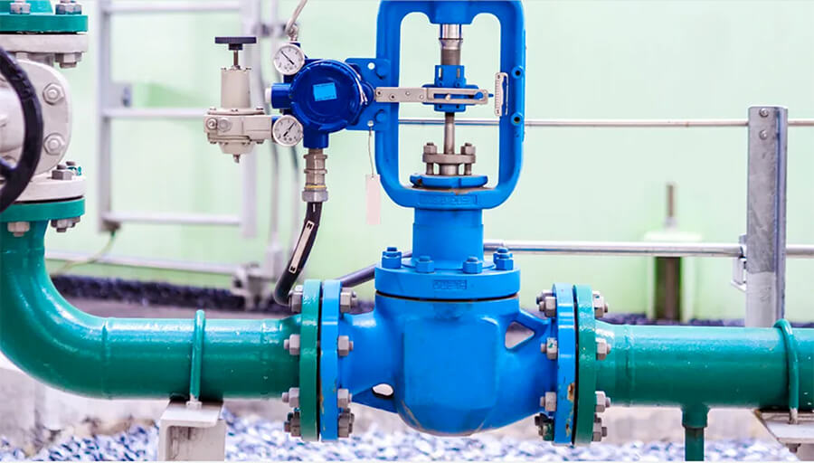
It is a valve that uses the disc to control the opening and closing. By changing the gap between the valve disc and the valve seat, that is, changing the size of the channel section to adjust the medium flow or cut off the medium passage. When installing the globe valve, attention must be paid to the flow direction of the fluid.
The principle that must be followed when installing the globe valve is that the fluid in the pipeline passes through the valve hole from bottom to top, commonly known as "low in and high out", and reverse installation is not allowed.

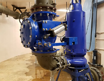
Check valve, also known as check valve and one-way valve, is a valve that automatically opens and closes under the pressure difference between the front and back of the valve. Its function is to make the medium flow in one direction only and prevent the medium from flowing back in the opposite direction.
According to the structure of the check valve, there are lifting type, swing type and butterfly wafer type. Lift check valves are divided into horizontal and vertical.
When installing the check valve, attention should also be paid to the flow direction of the medium, and it cannot be installed backwards.
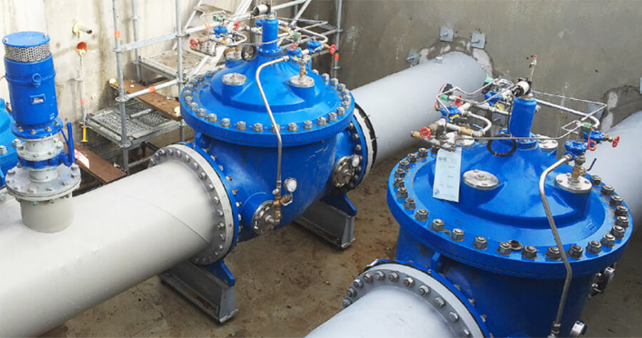
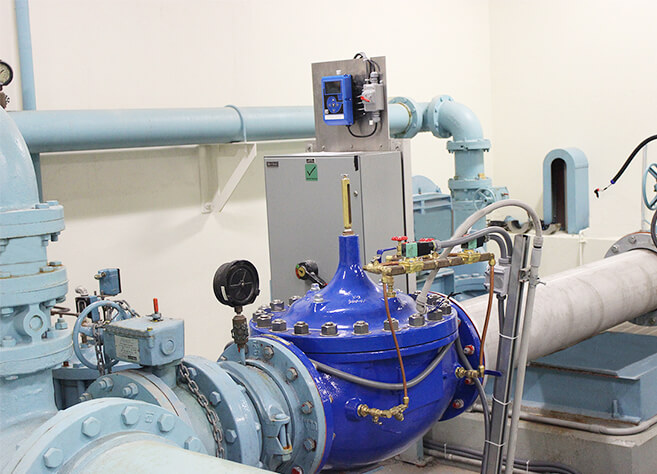
1. The vertically installed pressure reducing valve group is generally installed along the wall at a suitable height from the ground; the horizontally installed pressure reducing valve group is generally installed on a permanent operating platform.
2. The application section steel is respectively loaded into the wall on the outside of the two control valves (often used for globe valves) to form a bracket, and the bypass pipe is also stuck on the bracket for leveling and alignment.
3. The pressure reducing valve should be installed upright on the horizontal pipeline without tilting. The arrow on the valve body should point to the flow direction of the medium and should not be installed backwards.
4. Stop valves and high and low pressure gauges should be installed on both sides to observe the pressure changes before and after the valve. The diameter of the pipe behind the pressure reducing valve should be 2#-3# larger than the diameter of the inlet pipe before the valve, and a bypass pipe should be installed for easy maintenance.
5. The pressure equalizing pipe of the film pressure reducing valve should be connected to the low pressure pipe. For low-pressure pipelines, safety valves should be installed to ensure the safe operation of the system.
6. When used for steam decompression, a drain pipe should be installed. For piping systems that require a higher degree of purification, set a filter before the pressure reducing valve.
7. After the pressure reducing valve group is installed, the pressure reducing valve and safety valve should be tested, flushed and adjusted according to the design requirements, and the adjusted mark should be made.
8. When flushing the pressure reducing valve, close the inlet valve of the pressure reducer and open the flushing valve for flushing.
1. Cut-off valves (stop valves) must be installed before and after, and a filter should be installed between the trap and the front cut-off valve to prevent the dirt in the condensed water from blocking the trap.
2. An inspection pipe should be installed between the trap and the rear shut-off valve to check whether the trap is working normally. If a large amount of steam is released from the inspection pipe, it means that the trap is broken and needs to be repaired.
3. The purpose of setting up the bypass pipe is to discharge a large amount of condensed water at startup and reduce the discharge load of the trap.
4. When the steam trap is used to remove the condensed water of the heating equipment, it should be installed at the lower part of the heating equipment, so that the condensate pipe is vertically returned to the steam trap to prevent the heating equipment from storing water.
5. The installation location should be as close as possible to the drainage point. If the distance is too far, air or steam will accumulate in the slender pipe in front of the trap.
6. When the horizontal pipeline of the steam main pipe is too long, the drainage problem should be considered.
1. Before installation, the product must be carefully inspected to verify whether there is a certificate of conformity and product instructions, so as to clarify the constant pressure when leaving the factory.
2. The safety valve should be arranged near the platform as much as possible to facilitate inspection and maintenance.
3. The safety valve should be installed vertically, the medium should flow from bottom to top, and the verticality of the valve stem should be checked.
4. In general, cut-off valves cannot be installed before and after the safety valve to ensure safety and reliability.
5. Safety valve pressure relief: when the medium is liquid, it is generally discharged into a pipeline or a closed system; when the medium is gas, it is generally discharged to the outdoor atmosphere.
6. The oil and gas medium can generally be discharged into the atmosphere, and the outlet of the safety valve vent pipe should be 3m higher than the surrounding higher structures, but the following conditions should be discharged into the closed system to ensure safety.
7. The diameter of the inlet pipe should be equal to the inlet pipe diameter of the valve; the diameter of the discharge pipe should not be smaller than the outlet diameter of the valve. The discharge pipe should be led outdoors and installed with an elbow so that the pipe outlet faces a safe area.
8. When the safety valve is installed, when the connection between the safety valve and the equipment and pipeline is open-hole welding, the diameter of the opening should be the same as the nominal diameter of the safety valve.