Case
Home / Case / Experience / Six common valves installed in the pipeline
Case
Gate valve, also known as gate valve, is the use of gate to control the opening and closing of the valve, by changing the cross-section to regulate the pipeline flow and open and close the pipeline.
Gate valve is mostly used for the fluid medium to do full opening or closing operation of the pipeline. Gate valve installation is generally no directional requirements, but can not be installed upside down.
Globe valve is the use of valve flap to control the opening and closing of the valve. By changing the gap between the valve flap and the valve seat, that is, to change the size of the channel cross-section to regulate the media flow or cut off the media path. Installation of globe valves must pay attention to the direction of flow of fluid.
Installation of globe valves must comply with the principle that the fluid in the pipeline from the bottom up through the valve hole, commonly known as "low into the high," not allowed to install the reverse.
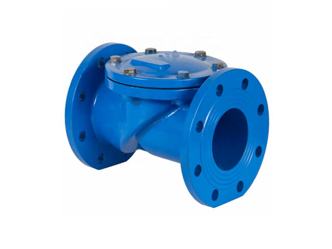
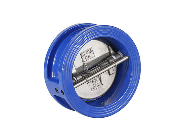
Check valve, also known as check valve, check valve, is a valve before and after the pressure difference between the valve automatically open and close the valve, its role is to make the medium only do a direction of flow, and to prevent the medium from flowing backwards and forwards.
Check valve according to its structure, there are lifting type, rotary opening type and butterfly clamp type. Lift check valve and horizontal and vertical points.
Installation of check valves, should also pay attention to the direction of flow of media, can not be installed in reverse.
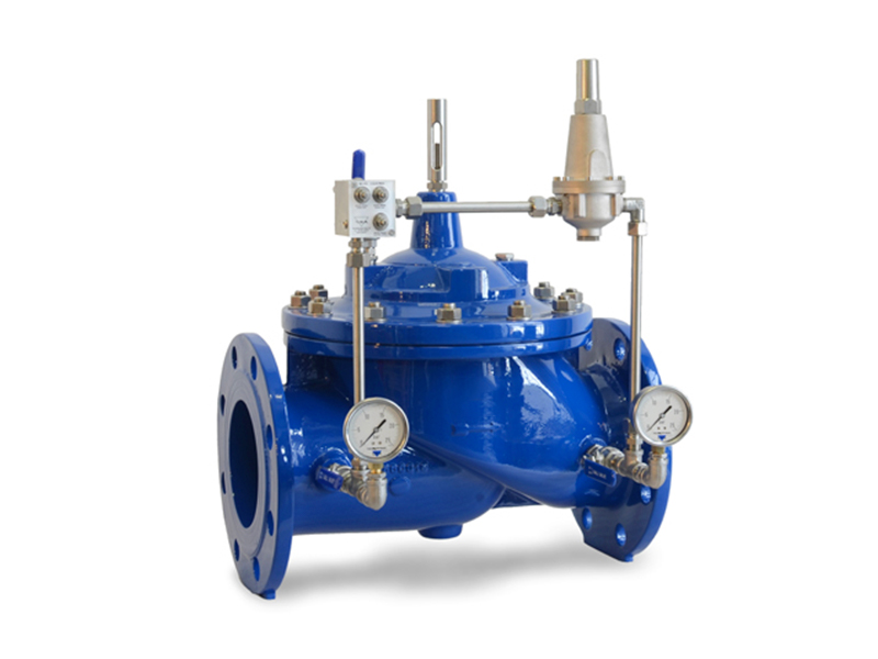
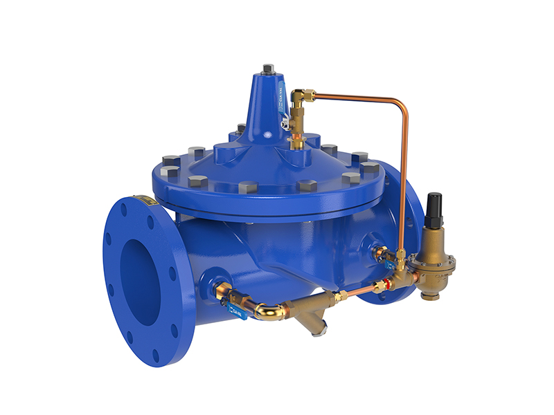
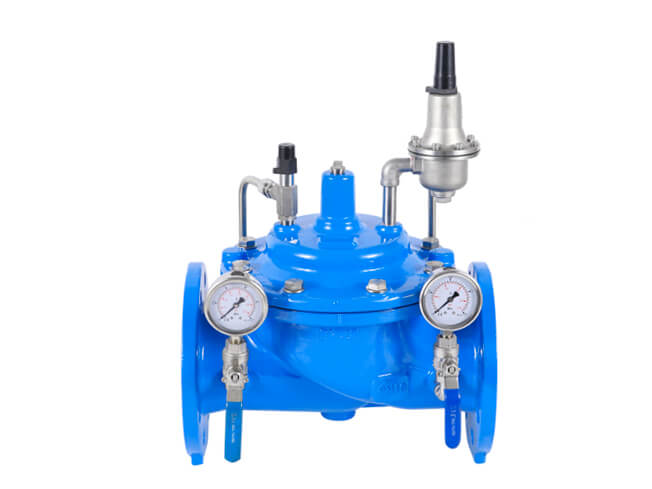
1. Vertical installation of pressure reducing valves, generally set along the wall at a suitable height from the ground; horizontal installation of pressure reducing valves, generally installed in the more durable operating platform.
2. The application of steel in the two control valves (commonly used in globe valves) are loaded into the wall on the outside, constitute a bracket, bypass pipe is also stuck in the bracket, levelling and finding the right.
3. The pressure reducing valve should be installed in the horizontal pipeline upright, not tilted, the arrow on the valve body should point to the direction of media flow, not installed in the opposite direction.
4. Stop valves and high and low pressure gauges should be installed on both sides to observe the pressure changes before and after the valve. The diameter of the pipeline after the pressure reducing valve should be 2#-3# larger than the diameter of the inlet pipe before the valve, and install a bypass pipe for maintenance.
5. The pressure equalisation pipe of the diaphragm type pressure reducing valve should be connected to the low pressure pipe. Low-pressure piping, safety valves should be installed to ensure the safe operation of the system.
6. When used for steam pressure reduction, a drain pipe should be set. For piping systems requiring a high degree of purification, set a filter in front of the pressure reducing valve.
7. After the installation of pressure reducing valves, pressure reducing valves and safety valves shall be pressure tested, flushed and adjusted according to the design requirements, and the adjusted mark shall be made.
8. When flushing the pressure reducing valve, close the pressure reducer inlet valve and open the flushing valve for flushing.
1. Cut-off valves (shut-off valves) should be set up both before and after the trap, and a strainer should be set up between the trap and the front cut-off valve to prevent the trap from being blocked by dirt in the condensed water.
2. An inspection tube should be provided between the trap and the rear shut-off valve to check whether the trap is working properly. If a large amount of steam is emitted when the inspection tube is opened, the trap is broken and needs to be serviced.
3. A bypass pipe should be provided to discharge a large amount of condensate during start-up to reduce the drain load of the trap.
4. When the trap is used to remove condensate from heat-using equipment, it should be installed in the lower part of the heat-using equipment so that the condensate pipe returns vertically to the trap to prevent the heat-using equipment from storing water.
5. The installation location should be as close as possible to the point of discharge, if the distance is too far, air or steam will accumulate in the slender piping in front of the trap.
6. When the horizontal piping of the steam trunk is too long, the problem of trapping should be considered.
1. Before installation, the product must be carefully inspected to verify whether there is a certificate of conformity and product specification, so as to make clear the factory pressure setting situation.
2. The safety valve should be arranged near the platform as far as possible for inspection and maintenance.
3. Safety valves should be installed vertically so that the medium flows out from the bottom upwards, and the verticality of the valve stem should be checked.
4. In general, the safety valve can not be set before and after the cut-off valve to ensure safety and reliability.
5. Safety valve pressure relief: when the medium is liquid, generally discharged into the pipeline or closed system; when the medium is gas, generally discharged to the outdoor atmosphere.
6. Oil and gas media can generally be discharged into the atmosphere, the safety valve vent pipe outlet should be higher than the surrounding higher structures 3m, but the following conditions should be discharged into the closed system to ensure safety.
7. Population pipe diameter, the smaller should be equal to the inlet diameter of the valve; discharge pipe diameter shall not be smaller than the outlet diameter of the valve, the discharge pipe should be led to the outdoors, and installed with a bend, so that the pipe outlet towards the safety zone.
8. Safety valve installation, when the safety valve and equipment and piping connection for the open hole welding, the diameter of the open hole should be the same as the nominal diameter of the safety valve.
Previous Valve O-ring