Case
Home / Case / Experience / Electromagnetic flowmeter installation

Case

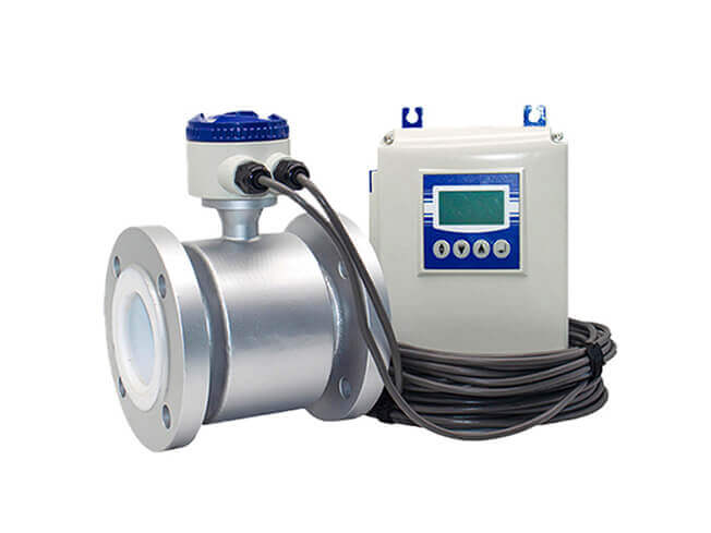
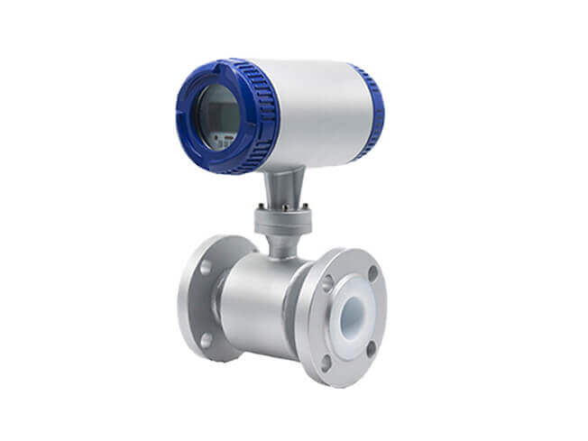
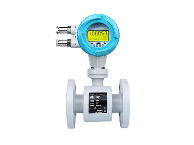
Electromagnetic flowmeter is the most common flow measuring instrument in industrial production. In order to ensure that the instrument can work normally and stably in production, there will be a series of problems that need our attention during the process of instrument installation and debugging. There are often some typical failures, so for a stable and normal working flowmeter, every link of installation and commissioning is very important. WESDOM GROUP as a professional Electromagnetic flowmeter manufacturers and professional service providers have accumulated a lot of experience in the process of serving customers for a long time. There is a complete set of solutions for these. The following points will be introduced one by one for you.
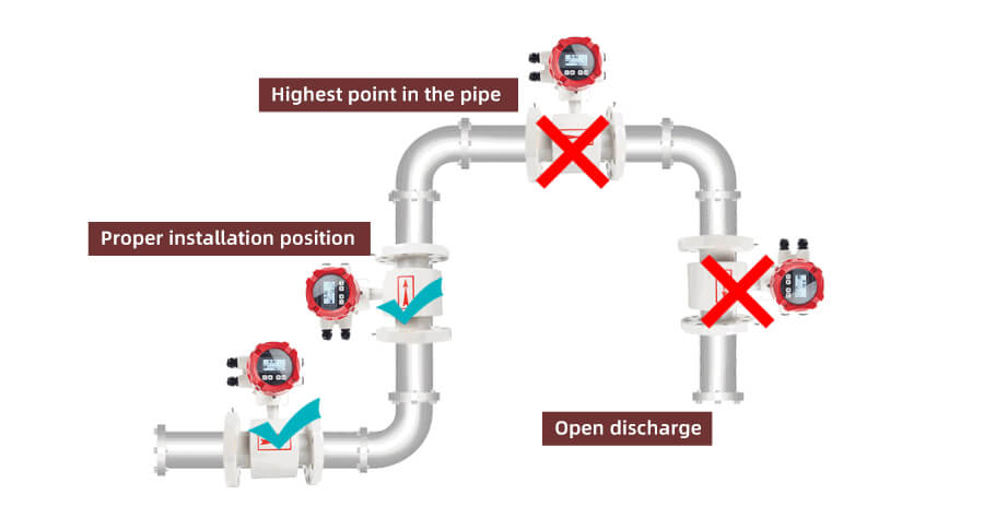
1. The electromagnetic flowmeter can be installed at any position on the running pipeline, and vertical installation is preferred. When installed horizontally or inclined, the axes of the two electrodes must be in a horizontal position
2. If the direction of liquid flow is consistent with the direction of the arrow on the nameplate of the electromagnetic flowmeter. Opposite flow directions cause opposite polarities.
3. When installing, keep the seal, grounding ring and measuring tube of the sensor in the concentric position to avoid eddy current.
4. There should be no ferromagnetic substances close to the meter, and the installation position of the electromagnetic flowmeter should be as far away from strong electromagnetic fields as possible.
5. It is required that the measuring tube is completely filled with liquid, and no part-full tube phenomenon is allowed.
6. Valves with flanges cannot be directly connected to the front or back of the sensor. Because the valve will also cause fluid disturbances and increase measurement errors, such a direct installation is not allowed under any circumstances.
7. The electromagnetic flowmeter cannot have spoilers within 5D upstream. Baffles, valves or spools shall be installed at least 2DN from the downstream side of the sensor.
8. When carrying and hoisting the instrument, do not use a tube or handle to fit into the measuring tube or use a rope to pass through the measuring tube for hoisting to avoid damage to the lining. Instead, hang the rope around the neck of the measuring tube.
9. In the case of serious pollution of the medium, the electromagnetic flowmeter is installed on the bypass pipeline. This installation method can open the valve and clean it mechanically without interrupting the operation.
Like ordinary instruments, after the installation and wiring of the electromagnetic flowmeter is completed, and before it is officially put into operation, the following installation and wiring should be checked for correctness and whether the instrument can work normally.
It must be emphasized here that the entire set of electromagnetic flowmeters has been adjusted and calibrated on the flow calibration device of the manufacturer. As long as the matching numbers of the sensors and converters and the meter coefficients are checked, they can generally be put into operation without any adjustment.
For some units that lack experience in use, the instrument installation and operation personnel should carefully read the relevant technical instructions in the relevant electromagnetic flowmeter installation and operation instructions, and be good at analyzing and thinking about the problems encountered in the initial operation. Before the instrument is put into operation, the sensor must be filled with the actual measurement medium, and the zero point adjustment should be made in a static state after power-on. After being put into operation, it is also necessary to stop the flow and check the zero point regularly according to the medium and use conditions, especially for non-clean media that are easy to precipitate, easily pollute electrodes, and contain solids. In the initial stage of operation, more inspections should be made to gain experience and determine the normal inspection cycle.
For qualified users, several basic parameters of the sensor should be measured and recorded before the instrument is put into operation.
① Electrode insulation resistance (when the sensor is empty, the insulation resistance of the two resistances to the instrument shell or ground);
②Insulation resistance of excitation coil (insulation resistance of excitation coil to instrument case or ground);
③The cold resistance value of the excitation coil (that is, the copper resistance value of the enameled wire of the excitation coil);
④ Electrode contact resistance The sensor is filled with liquid, measure the resistance value between the electrode and the grounding terminal, the contact resistance value of the two electrodes should be roughly the same.